|
|
|
Xmt-4000 temperature controller (temperature regulator)
Product Name: xmt-4000 temperature controller (temperature regulator)
Product No.: 165852-729
Product model: xmt-4000
Updated on: July 1, 2009
Manufacturer: thermocouple, thermal resistance, bimetal thermometer, polytetrafluoroethylene, PTFE gasket -- Shanghai Feilong instrument and Electrical Co., Ltd
Product details
Xmt-00 Series Intelligent Expert PID
Industrial control / regulator
Xmt-4000 Series Intelligent Expert PID
30 segment programmable industrial control / regulator
(1) . function description
Xmt-4000 series programmable temperature control / regulator (for the sake of simplification, it will be described later that xmt-4000) instrument is based on xmt-3000 series instrument. The hardware structure of the two instruments is identical, so the technical specifications and parameters of the instrument are roughly the same. Xmt-4000 series instruments are compatible with the functions of xmt-3000 series instruments (but xmt-4000 series instruments cancel the manual operation function), and add the user programmable time control function. The programming curve can reach up to 30 segments, and there are two event output functions. Xmt-4000 series meters and xmt-3000 series meters have the same panel, but their operation methods are quite different. Xmt-4000 series instruments do not have three functions: transmitting output, external setting and direct valve control.
Before using xmt-4000 series instruments, users should read the operation manual of xmt-3000 series intelligent special energy PID industrial regulator. Read this manual again, and then you need to correctly master the wiring of the instrument, and then you need to master the meaning of each parameter of the instrument and be able to set the parameters of the instrument according to your own needs.
Xmt-4000 series instrument is used in the situation that the given value needs to be changed automatically according to a certain time rule for control. It has advanced design, powerful programming and operation ability, high anti-interference and high reliability structure, which can widely meet the requirements of different users and further improve the automation level of control equipment. The main features of xmt-4000 series instruments are as follows:
1. 30 section degree control, can set any size of rise and fall temperature (or pressure, flow, humidity, etc.) slope.
2. Programming and operation are very flexible, with jump (cycle), operation, pause and stop and other programmable / operational commands. And it is allowed to modify the program at any time during the program control operation.
3. Two channel event output function. The interlock action of other equipment can be controlled through the alarm output to further improve the automation ability of the equipment.
4. The option of external control input switch, through the external switch to execute program operation / pause / stop and other operations, can realize interlocking, synchronous start operation and other functions, and facilitate the operation of workers.
5. Expert PID control mode, no overshoot and undershoot excellent control characteristics, with curve fitting function, can obtain smooth curve control effect.
6. It has the function of starting and preparing the measured value, which makes the program execution more efficient and perfect.
7. There are four kinds of power failure / start-up event processing modes, which can perfectly solve the impact of unexpected power failure on program control.
(2) . model definition
The model definition of xmt-4000 series instrument is exactly the same as xmt-3000 series instrument. Please refer to the operation manual of xmt-3000 Series Intelligent Expert PID industrial regulator. The difference is that xmt-4000 series instruments cannot be installed with transformer output module in auxiliary function position, but it is allowed to install external control input interface module for external operation such as program running / pause and stop.
2、 Panel description and operation instructions
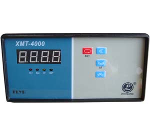
(1) Panel instruction (take xmt-4000a instrument as an example)
① PV - measurement value display ⑥ al2 - alarm light
② SV - set value display ⑦ set - set value
③ Out - output indicator light ⑧ < (at) - shift key
④ Run - program running light ⑨∧ - add key
⑤ Al1 - alarm light 10 ∨ - decrease key
When setting the program: ① the upper display window displays the program code, such as C01, T01, etc., and the lower display window displays the program value. If there is no key operation in this state, it can only be maintained for about 10 seconds, and then it will automatically return to the state of displaying the measured value.
Operation status: the upper display window displays 4-digit measured value, and the lower display window displays 4-digit given value.
* pause state: the upper display window displays the measured value, and the lower display window alternately displays the symbol of the given value and "hold".
※ stop status: the upper display window displays the measurement, and the lower display window alternately displays the symbol of the given value and "stop".
Time display: if the operation of time display is performed, the upper display window shows the time set for the current program segment, and the lower display window shows the time that has been run. Even if the set key is not pressed to exit the time display state, it will automatically return to the state of displaying the measured value after about 30 seconds.
* run indicator light: when the program stops running, the light is off; when the program is running normally, the light is on; when the program is running but stops timing, that is, under the status of pause, preparation or self-tuning, the light flashes.
(2) . operating instructions
1. Setup program: press the < key once to release, and the instrument will enter the setup program state. The instrument first displays the given temperature at the beginning of the current operation section, and then the decimal point of the last digit (one digit) of the displayed data starts to flash (like the cursor). Press the key ∨ to decrease the data, press the key ∧ to increase the data, and press the key < to move the position (cursor) of the modified data. After changing the given temperature to a suitable value, press set again to display the next program value to be set (current period time), and each program is arranged in order of temperature, time, etc. The instrument allows the program to be modified while the program is running. When setting the program, first press the < key and keep it in place, then press the set key to exit the setting program status in advance, and then press the ∨ key to return to the previous value. Note that if the program setting has been locked (see the introduction of LOC parameter later), the above operation of setting the program value cannot be performed.
2. Set parameters: press the set key and hold for 2 seconds, and then release it after the parameters are displayed. Press the set key again, the instrument will display all parameters according to this, such as the upper limit alarm value hial, parameter lock LOC, etc., and the parameter value can be modified through the keys of <, ∨, ∧. In the setting parameter state, first press the < key and keep it, then press the set key to exit the setting parameter state, and then press the ∨ key to return to check the previous parameter, but if the parameter has been locked by the LOC, the function cannot be performed.
If the parameters are locked by the LOC (described later), only the field parameters defined by the EP parameters (which can be defined by the user and are often needed in the work site) can be displayed, but other parameters cannot be seen. However, at least you can see the LOC parameter displayed.
3. Display and modify program moving segment number (stip): in program operation, sometimes you want to start from a certain segment of the program, or jump directly to a certain segment of the program, for example, the current program has run to segment 4, but you need to end the segment in advance and run segment 5, then you can perform the function of modifying program running segment number. Xmt-4000 series can execute programs from any section of 30 program sections by setting the step. If the temperature curve that the user needs to run is less than 30 segments, the instrument also allows the user to set up multiple different curve programs and execute them separately, as long as their total number of segments (including necessary control segments) does not exceed 30 segments. For example, if a process curve is a 9-segment program, the instrument can set three such similar curves. In the production process, different curves can be called by changing the stip.
To modify the stip value, press the set key to release it, and the instrument will display the stip value, which can be modified by ∨, ∧, etc. In general, the stip automatically increases or jumps with the execution of the program. If the value is changed artificially, the running time of the segment is cleared to 0, and the program starts from the starting position of the new segment. If you press set to exit without changing the stip value, the program operation will not be affected.
4. Display the running time: when the step is displayed, press the set key once again to release, then the display on the instrument will display the running time of the current section, and the lower display will display the running time of the current section. In this state, press the set key once again to release, then return to the PV and SV display states.
5. Modify the program curve during operation: in the constant temperature section, if you want to increase (or decrease) the current given temperature, you need to increase (or decrease) the current given temperature and the next given temperature at the same time. If you want to increase or shorten the holding time, you can increase or decrease the time of the current section. If you want to change the slope of the temperature rise / fall in the rise / drop section, you can change the time of the section, the given temperature of the current section and the given temperature of the next section as needed. If the start function of the measured value is allowed, the instrument will try to make the given value consistent with the measured value by changing the operation time after each modification of the data in the heating or cooling section. Measured value start function is invalid for constant temperature section.
6. Run / hold: press the key ∨ in the stop state and hold for about 2 seconds until the run symbol is displayed on the display under the instrument, then the instrument starts to run the program. Press the ∨ key in the running state and keep it for about 2 seconds until the symbol of hold is displayed on the display under the instrument, the instrument will enter the pause state. In the state of pause, preparation and self-tuning, the run indicator flashes; in the state of run, the run indicator lights up. Pause means that the instrument still performs control and controls the given value at the given value during the pause. The time stops increasing and the running time and the given value will not change. Press the ∨ key in the pause state and hold for about 2 seconds, until the run symbol is displayed on the display under the instrument, the instrument will run again.
7. Stop: press the∧key and hold for about 2 seconds until the stop symbol is displayed on the display under the instrument, at this time, the instrument performs the stop operation. This operation causes the instrument to enter the stop operation state. At the same time, the step is modified to 1, the output is cleared, and the control output is also stopped. When the user needs to execute the program again, run operation can be executed. At this time, the program starts to run again from the first paragraph.
8. Self tuning (at): the instrument self-tuning function should be used to determine the control parameters (M50 / P / T parameter value) for the first time to achieve the ideal control. Note: the parameter values of the system adjusted under different given values are not identical, so when the self-tuning function needs to be executed, the program should be run to the most commonly used given value first, and then the operation function of starting the self-tuning should be executed. Press the < key at the initial start-up self-tuning time and hold for about 2 seconds, wait until the display under the instrument displays "at" and then release. (if it has been started once, the operation function cannot be executed. In this case, the application parameter sets Ctrl to 2 to start self-tuning, see the parameter description). After 2-3 on / off operations, the microprocessor in the instrument calculates the optimal control parameters by analyzing the period, amplitude and waveform of the oscillation generated by the bit control. The instrument automatically adjusts the control parameters and starts to implement the precise expert PID control. If you want to give up the self-tuning, press the < key in the self-tuning state and keep it for about 2 seconds. Wait until the "at" on the display under the instrument stops flashing. Generally, the self-tuning only needs to be performed once. After the self-tuning of the instrument, the parameter Ctrl will be set to 3 (1 at the factory), so that the self-tuning can not be started again by pressing the < key from the panel, so as to avoid human misoperation.
The bit type control is used in the self-tuning, and its output is located at the position defined by the parameters of OPL and OPH. In some cases where the output does not allow large changes, such as some valve control. Adjust OPL and OPH to reduce the output range and limit the output to the allowable range. After the self-tuning, change OPL and OPH back to the original position.
3、 Conceptual interpretation
The operation of xmt-4000 instrument is complex, so some of its terms are explained in the following.
The segment number of the program can be from 1-30, and the current segment (stay) indicates the currently executing segment.
Period time refers to the total running time of the program section, unit: minute, valid value: 1-9999.
Running time refers to the time when the previous section has been running, and when the running time reaches the set period, the program will automatically move to the next section.
The jump program section can be programmed to automatically jump to any section of section 1-30 for execution, which can realize cycle control. You can also jump by changing the value of the stip. In addition, if the program segment number has run to segment 30, it will automatically jump back to segment 1.
When the running / pause program is in the running state, the time is timed and the given value changes according to the preset curve. When the program is in the pause state, the time stops and the given value remains unchanged. The instrument can program pause operation in the program section. When the program encountered a set period of time is 0, or jump to jump or jump to jump section (Hou Wen introduced), the program will enter the pause state. The pause / run operation can also be performed by a person at any time.
Stopping the execution of the stop operation will stop the program. At this time, the running time is cleared and the timing is stopped. The event output switch is reset and the control output is stopped. When running operation is performed in the stop state, the instrument will start the running program from the segment number set by the stip. The function of automatic stop can be programmed in the program segment setting, and the value of the run segment No. stip can be set at the same time. You can also perform stop operation at any time (after execution, the step is set to 1, but the user can modify it again).
Power failure / start-up event refers to the power on of the instrument or unexpected power failure during operation. In the following article, four processing schemes are introduced for users to choose.
Event output event output occurs by programming. It can control the action of two alarm switches in the process of program operation, so as to control the synchronous or interlocking work of various external equipment.
When the measured value start-up value starts the operation procedure, after the unexpected power failure / start-up, but needs to continue to run the procedure, or when the step value or program value is manually modified, it often causes the measured value to be inconsistent with the given value. The instrument can adjust the operation time to ensure the consistency of the two values.
If the measured value is different from the given value (if the measured value is allowed to start the function, the system first uses the measured value start function for processing, and only the preparation function that does not meet the processing conditions of the measured value start function is used for processing), and the difference is greater than the positive value when the running program is started, the unexpected power failure / start but the program needs to be run, or the step value or program value needs to be manually modified( Or negative) deviation alarm value, (dhal and dlal), the instrument does not immediately carry out positive (or negative) deviation alarm, but first adjust the measured value to the error less than the deviation alarm value, at this time, the program also stops timing until the positive and negative deviation meet the requirements before starting the program. It is also useful to use the preparation function to set the unpredictable rise / fall time. To turn off the preparation function, set the dhal and dlal large enough.
Note also that if an alarm exists and is defined to be output through alarm switch 1, paragraph 6 cannot turn off alarm switch 1, because an alarm can also turn on the alarm switch.
The advantage of temperature time programming method is that the slope setting range of temperature rise and temperature fall is very wide. The heating and constant temperature section has a unified setting format, which is convenient for learning. The setting curve is more flexible, or the heating section can be set continuously (for example, the heating section with different slope can realize the function heating approximately), or the constant temperature section can be set continuously.
(1) Time setting
TXX = 1-9999 (min) indicates the time value set in the XX segment.
TXX = 0 the instrument enters the hold state in the XX section, where the program stops temporarily.
TXX = - 1-240 negative time value indicates a control command. To control the program running stop, jump and two-way event output.
Meaning: TXX = - (a * 30 + b)
The value of B is 1-30, indicating that the program jumps to the segment indicated by the value of B
A = 0, no effect (only perform jump function).
A = 1, turn on alarm switch 1.
A = 2, turn on alarm switch 2.
A = 3, turn on alarm switches 1 and 2 at the same time. Three
A = 4, the instrument performs stop operation, and b value has different meanings. At present, it should be set to 1, and 2-30 has standby meanings.
A = 5, turn off alarm switch 1.
A = 6, turn off alarm switch 2.
A = 7, turn off alarm switches 1 and 2.
For example: the fourth paragraph of the above example program is defined as: skip to the fifth paragraph and turn on the alarm switch 1.
Then set: t 04 = - (1 * 30 + 5) = - 35
Another example: the sixth paragraph of the above example program is defined as jump to the first paragraph and turn off the alarm switch 1.
Then set: t 06 = - (5 * 30 + 1) = - 151
Another example: suppose that the program needs to stop at the end of the eighth segment.
Then set: t 08 = - (4 * 30 + 1) = - 121. This is the setting to stop running the program.
After the program is automatically finished in the eighth segment, the program will run from the first segment after the user performs the run operation.
Note: the skip operation can be continued except when the skip section is encountered during operation or power on. When the control program of the skip section jumps to the control section during the operation of the program, the program automatically pauses execution (that is, the instrument automatically inserts the pause operation in two consecutive jumps), and the external run / hold key operation is required to release the pause state. Note that if the jump segment jumps to itself (for example, t 06 = - 6), it will not be able to release the pause state, because such a segment can be said to be meaningless. So in the program of the above example, the fifth paragraph (pause operation paragraph) can also be omitted, but in order to make the program easy to read, we suggest adding this paragraph.
(2) Given value setting
The range of values that can be set for a given value is - 1999 - + 9999, indicating the temperature value to be controlled (℃) or the line definition unit.
(3) Program input operation
Press the < key, the instrument will enter the program input setting state. The temperature value of the first segment is displayed first. Then press the set key in turn to display the time value and temperature value of the first and subsequent segments. For example, the program display in the previous example should be:
Key up display down display description
< C 01 100 the first stage temperature is 100 ℃
The first period of set t 01 30 is 30 minutes
Set C 02 400 temperature of the second section is 400 ℃
The second period of set t 02 60 is 60 minutes
Set C 03 400 temperature of the third section is 400 ℃
The display value of the lower display is a numerical value, which can be modified with the keys of <, ∨, ∧. The rest of the operation has been described in detail.
(4) Programming method when running multiple curves
Xmt-4000 series instruments have flexible and advanced programming methods. Since the instrument will automatically set the stip to 1 after stop, if the stip value is not modified before start-up and operation, the re operation will generally start from the first section. For users with multiple temperature control curves, the method of setting the first segment as jump segment can be used to execute different curves respectively. If the user has three curves with 8 segments in length, the program can be arranged in 2-9, 10-17, 18-25. To execute different curves after reset, the first segment (jump segment) shall be set as follows:
T 01 = - 2; indicates that the first curve (2-9) is executed during operation
T 01 = - 10; indicates that the second curve (10-17) is executed during operation
T 01 = - 18; indicates that the third curve (18-25) is executed during operation
When the production process needs to be changed, as long as "t 01" is set to - 2, - 10 or - 18 respectively, the operation can start to run different curves respectively. This jump segment can also be omitted, but it is enough to set the stip as the starting segment of the required running curve before each start-up operation.
(5) External event input interface
Xmt-4000 instrument can be installed with external event input control interface module at the auxiliary function position of the instrument. After installing this option, the instrument is not allowed to install the communication interface function. Xmt-4000 instrument with this option can use external switch to control program pause / operation and stop function. The purpose of this function is as follows: 1. Multiple instruments operate synchronously or stop synchronously; 2. It is convenient to operate. Using this interface, the operation / pause and stop buttons can be installed on the control cabinet, so that the operator does not need to contact the instrument, which is convenient for the workers to master; 3. It can use the equipment like programmable controller to control the instrument linkage. The interface is located at the auxiliary function of the instrument, see the instrument wiring diagram, and the wiring diagram of the external switch is as follows. The external control interface shall be equipped with button switch without self-locking. Press the switch run / hold, and the instrument performs the run / pause operation. Press stop to stop the instrument.
Note: 1. In order to prevent misoperation, it is required that the operator's button stay longer than 0.3 seconds to ensure reliable operation.
2. Parameter CF must be set correctly, otherwise it will think that the auxiliary function of the instrument is the communication interface and cannot work.
5、 Power failure handling
For the xmt-4000 instrument, the run parameter defines the event handling mode when the program is running.
The sudden actions that can affect the control and execution of programs are called events. Events often have the possibility of producing unexpected results. Event handling is to make these unexpected situations into predictable results.
Run=A*1+B*4
Among them, a is used to select 4 power failure / startup event processing modes, and B is used to select 2 operation / modification processing modes. Power off / power on event handling mode.
The power failure / startup event processing of xmt-4000 instrument is an important function. The purpose of program temperature control is to improve the automation level of the equipment, so as to improve the production speed, improve the product consistency and qualification rate, and reduce the human adverse factors. But in a production condition with power failure, if the power failure is handled improperly, the normal execution of temperature control program will be interrupted, leading to the failure of production. Xmt-4000 has power failure processing function. Users can set it according to their own process needs to avoid the loss caused by power failure as much as possible.
After power failure, the instrument can reliably save the current section number, 30 program sections, event output status, operation / pause / stop status and operation time. They are all stored in advanced EEPROM devices and can be stored for 10 years. And recover or handle when the power is on.
Xmt-4000 instrument can select four power failure processing functions, and the setting function of a in run parameter can be expressed as follows:
A = 0, no matter what the situation is, it will be transferred to the 29th section for fault handling after power on, such as turning on the event output switch for alarm, etc.
A = 1, if there is no deviation alarm after power on, it will continue to execute at the original termination, and the event output status will remain unchanged. Otherwise, it will be executed from segment 29 and the event output status will be cleared. This method is suitable for the application with high technological requirements.
A = 2, continue to execute at the original termination after the instrument is powered on, which is suitable for the application where the power failure does not affect the production.
A = 3, no matter what happens after power on, the instrument will enter the stop state. It is suitable for the situation of power failure.
Run / modify event handling
When xmt-4000 instrument performs run operation, power off / power on and needs to continue running program (power off / power on event processing first), the user modifies the running program value of current segment (current segment given value, current segment time or next segment given value) or the SEP value, the instrument is collectively referred to as run / modify event. When the running / modifying event occurs, the actual measured value of the instrument is often different from the given value calculated by the program, and this difference is often unpredictable because the user does not want to produce it, because it will make the program control inconsistent.
For example: for a temperature rise section program, set the temperature rise of the instrument from 25 ℃ to 625 ℃ after 600 minutes, temperature rise of 1 ℃ per minute, assuming that when the program starts from the starting position of the section, if the measured value is just 25 ℃, the program can be executed smoothly according to the original plan. However, if the measured value at this time is 100 ℃ (this often happens because the system temperature has not been reduced at the time of startup), then the program is difficult to implement smoothly according to the original plan. Xmt-4000 provides the following modes for users to choose to deal with such problems.
B = 0, normal mode. The program is executed according to the original plan. This mode ensures the fixed running time of the program, but cannot guarantee the integrity of the whole curve.
B = 1, start function of measured value, preset the running time according to the measurement. In the above example, the instrument will start to operate from the 75th minute position (at this time, the given temperature is 100 ℃), which can adjust the operation time according to the measured value. Compared with B = 0, this mode reduces the running time, does not guarantee the integrity of the whole curve, but can guarantee the consistency of the heating rate. In the constant temperature section, when the measured value is lower than the lowest temperature of the curve or higher than the highest temperature of the curve (for example, the measured value is lower than ℃ or higher than 625 ℃ when starting in the above example), the function will be cancelled, which is the same as when B = 0.
Preparation function: the preparation function of xmt-4000 type instrument is attached to the above two operation / modification event processing modes. Using the quasi function, the user is required to set appropriate deviation alarm parameters such as dhal and dlal, so that when the above operation / modification event occurs, if the deviation alarm condition is met, the instrument will first suspend the operation of the program, so that the operation time of the given value does not change, nor Output the deviation alarm signal, but control the measured value until the deviation alarm is released before continuing to run the program. If the B = 1 of the above run parameter, the system first performs the start function of the measured value, and then performs the preparation function. If the measured value start function can work effectively, the preparation function does not need to work, because at this time, the instrument has adjusted the system to the state without deviation alarm. When the start function of the measured value fails to work or B = 0, the operation preparation will work. This function can ensure the integrity of the whole program curve, but increase the operation time. The increased time is due to the preparation time. Both the preparation function and the measurement start function are used to solve the uncertainty of the program operation caused by the inconsistency between the measured value and the given value caused by the operation / modification event, so as to obtain the program operation result with high efficiency, integrity and meeting the user's requirements.
For example, the user requires that the instrument continue to execute in the original position after power on, and has the function of starting the measured value, and can set a = 2, B = 1. Then: run = 2 * 1 + 1 * 4 = 6
6、 Differences from xmt-3000 instrument
1. System run parameter run: the run parameter defines the event handling mode when the program runs, as described in Section 5.
2. Select LOC for parameter setting permission:
For xmt-4000 meters
LOC = 0, field parameters can be modified. Program value (time and temperature value) and program section number stip value.
LOC = 1, it is allowed to modify the field parameters and stip values, but not the program.
LOC = 2, field parameters can be modified. However, it is not allowed to modify the program stip value.
LOC = 3, all parameters except the LOC parameter itself can be modified. Neither the program nor the value of stip can be modified.
LOC = 808, all parameters and program stip values can be set. Note that 808 is the setting password of all xmt-4000 series instruments, and other values shall be set when the instrument is used to protect the parameters from arbitrary modification. At the same time, production management should be strengthened to avoid operating instruments at will.
If LOC is set to another value, the result may be one of the above, most of which is the same as LOC = 1.
3. Output definition parameter OP1:
The xmt-4000 instrument has no manual operation function, nor the regulating function of directly driving the valve. Therefore, the OP1 parameter cannot be set to 3 or the CTRL parameter cannot be set to 4.
4. Function parameter CF:
CF parameter is used to select some system functions:
CF=A*1+B*2+C*4+D*8
A = 0, which is the regulation mode of reaction, a = 1, which is the regulation mode of positive action.
B = 0, no power on for instrument alarm / alarm exemption function for modification of given value; b = 1
|