Product Name: pressure transmitter-fl102 differential pressure remote transmitter pressure transmitter-fl102 differential pressure remote transmitter
Product No.: 14816-672
Product model: fl102
Production unit: [thermocouple] - Shanghai Feilong instrument and Electrical Co., Ltd. 021-63801621
Product details
1, application
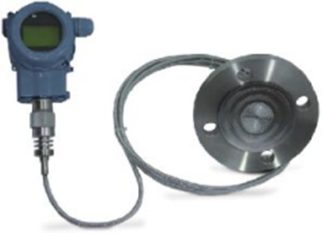
The membrane box of the differential pressure remote transmitter is used to prevent the medium in the pipeline from directly entering the pressure sensor assembly of the differential pressure transmitter. The filling liquid such as silicone oil is used to transfer the pressure between it and the transmitter.
Fl101 differential pressure remote transmitter is used to measure the liquid level, density, pressure and flow m of M liquid, gas or steam, and then convert it into 4 ~ 20mADC Hart current signal output. Fl101 can also communicate with rst375 handheld terminal or rsmioomodem for parameter setting, process monitoring, etc. Fl101 series differential pressure transmission
The M range of the device {when not moved) is 0-1kpa ~ 2MPa, and the rated pressure of the remote flange is 1.6/4mpa, 6.4Mpa, 10MPa, 150psi, 300PSI or 600psi, respectively
2. Working principle and structure
Fl101 differential pressure remote transmitter is composed of fl101 series differential pressure transmitter and welded remote flange with capillary. Its working principle is the same as that of fl101 series differential pressure transmitter (refer to the technical specifications of fl101 series differential pressure transmitter), but the pressure transmission path is slightly different: the pressure acting on the remote flange is first passed through the diaphragm and filling liquid on the remote flange, then through the capillary, finally to the corresponding positive and negative sides of the measurement sensor.
3. Input
Measurement parameters: differential pressure, liquid level
Measuring range:
Lower limit: - from 100% URL (continuously adjustable}
Lower limit: to + 100% URL (continuously adjustable}
Mileage: table comparison between 1m range code and * range
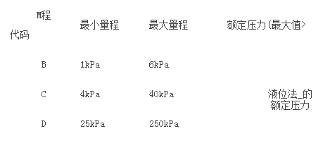
Table 2 Comparison between liquid level flange and minimum m range
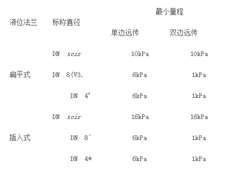
It shall be the minimum of the maximum range of transmitter body and the rated pressure of liquid level flange.
4, output
output signal
2 limit, 4-20madc Hart output, digital communication, HART protocol added on 4-20madc signal.
Output signal limit: 1min = 3.9ma, Lmax = 20.5ma
Reporting current (mode can be set)
Low alarm mode (minimum): 3.7 Ma
Low alarm mode (minimum): 21 Ma
Unreported mode (hold): keep the effective current value before the fault
Alarm current standard setting s: high alarm mode
5. Response time
The damping of amplifier components is usually 0.1s; the time constant of sensor and remote flange is 0.2s-6s, which depends on the m-pass, m-pass ratio of sensor, the length of capillary, and the viscosity of filling liquid.
6. General conditions
6.1 installation conditions
The transmitter body can be directly fixed to any position s. The best condition is to make the flange axis in the vertical state, and the deviation of bit a will produce the zero position deviation which can be corrected. The electronic watch can rotate 360 ° at most, and the positioning pin can fix it in any position.
The remote flange is connected with the matching flange conforming to ANSI / DIN standard. The matching flange shall be equipped with soft gasket and fixed butterfly bolt and nut (the user can choose to install the bolts and nuts). For double flange remote transmitters, capillary components and remote flanges should only be possible to be installed at the same ambient temperature. The minimum bending radius of the capillary is 75mm. It is forbidden to wrap it!
6.2 environmental conditions
Ambient temperature:
Minimum: depends on fill fluid
Maximum: 851
- 20-651 with liquid crystal display and fluororubber sealing ring
Storage temperature / transportation temperature:
Minimum: depends on fill fluid
Maximum: 851
Relative humidity: 0-100%
Impact resistance: acceleration: 50g duration: 11ms
Anti Leidong: 2G to 500Hz
6.3 process medium limit
Humidity limit
Medium temperature: - 20-65^
Table 3 Relationship among filling liquid, working temperature and minimum working static pressure
Medium temperature:
-20-65^
Table 3 Relationship among filling liquid, working temperature and minimum working static pressure
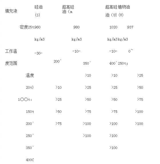
Note: in case of exceeding the above range of working temperature and static pressure, it shall be specially pointed out that the requirements can be met through special design.
Pressure limit of transmitter body: from 3.5kpa absolute pressure to rated pressure, the protection pressure can be greater than 1.5 parts of rated pressure, and it is added to two cases of transmitter.
Rated pressure of remote flange:
Ans standard: 150psi ~ 600psi
DIN standard: PN1.6MPa ~ pn10mpa
One way overload limit: the low-pressure side is the rated pressure of the transmitter body, and the high-pressure side is the rated pressure of the liquid level flange, which may cause
Zero drift that can now be corrected.
Weight: single side remote transmission: DN50 / 2 · about 7-10kg; DN80 / 3 "about 8-11kg; dn4m about 9-12kg;
DN50 / 2 μ is about 10 ~ 16.51 < 9; DN80 / 3 · is about 12 ~ 18kg; DN4 ■ is about 14 ~ 21kg;
Explosion proof performance
Neps flameproof license: Exd iict6
Nepsi intrinsic safety license: Exia iict4
Allowable service temperature: - 401-651
6.4 power supply and load conditions: the power supply voltage is 24V,
R (us-12v} / lmaxkq where Lmax = 23ma
Minimum supply voltage: 12VDC, 15Vdc {backlight LCD
Display}
Negative range of digital communication: 250 ~ 600q
Texture of material
Measuring capsule: stainless steel 316L
Diaphragm: stainless steel 316L, Hastelloy C, tantalum
Process connection: stainless steel 304
Filling fluid: silicone oil, high temperature silicone oil, ultra-high temperature silicone oil, vegetable oil
Sealing ring: NBR, FKM, PTFE
Transmitter outer cover: aluminum alloy material, outer surface sprayed with epoxy resin
Outer seal ring: NBR
Nameplate: stainless steel 304
Electrical connection:
M20x 1.5 cable sealing buckle, terminal is suitable for 0.5-2.5mm2 conductor.
Process connection:
There are NPT 1 / 4 and unf7 / 16 ? internal threads on the low pressure side of the transmitter. The level flange on the high pressure side of the transmitter complies with ANSI standard or DIN standard.
External protection class: IP67
Table 3 schedule of electromagnetic compatibility:
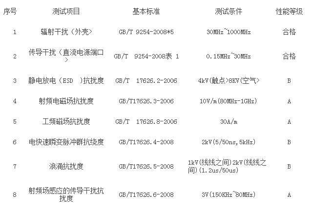
Note: (1) a performance level description: during the test, the performance is normal within the limit of technical specifications.
(2) B performance level description: during the test, the function or performance is temporarily reduced or lost, but can be recovered by itself, and the actual operating condition, storage and data are not changed.